Understanding Electric Motors
Overview of Electric Motors
Electric motors are the silent engines of modern progress, powering everything from industrial machinery to household appliances. Their complexity often conceals a fascinating simplicity—an intricate dance of magnetic fields and electrical currents. When you examine an electric motors diagram, you uncover the blueprint of ingenuity, revealing how these devices convert electrical energy into mechanical motion with astonishing efficiency.
Understanding the core principles behind electric motors involves recognizing the importance of components like the stator and rotor, which work together harmoniously. An electric motors diagram visually encapsulates these interactions, illustrating how magnetic forces induce rotation. It’s a snapshot of engineering mastery that, when decoded, offers profound insight into how power is harnessed and transformed in everyday life.
For those exploring the depths of electrical engineering, grasping the details within an electric motors diagram is essential. It’s not just about diagrams; it’s about understanding the very essence of motion and energy—an elegant testament to human innovation. Whether for maintenance, design, or innovation, mastering this visual language unlocks new perspectives on the machinery that drives our world.
Types of Electric Motors
Electric motors are an astonishing testament to human ingenuity, transforming our daily environment with silent efficiency. When exploring an electric motors diagram, one quickly appreciates the diversity and sophistication of these machines. Understanding the different types of electric motors—such as AC motors, DC motors, synchronous, and asynchronous variants—unveils a complex yet elegant tapestry of engineering mastery.
Each type of electric motor serves a unique purpose, optimized for specific applications across industries in South Africa. For instance, AC motors dominate in industrial settings due to their robustness and simplicity, while DC motors excel in precision tasks. Recognizing these distinctions enhances our ability to interpret an electric motors diagram accurately. It reveals how components like the stator and rotor collaborate to produce rotational motion, a process rooted in magnetic interaction and electric currents.
By delving into the intricacies of electric motors diagram, engineers and technicians can better appreciate the underlying principles that power everything from mining equipment to household appliances. The diagram is more than just a schematic; it is a window into a world where energy and motion intertwine seamlessly, embodying innovation in every turn of the rotor.
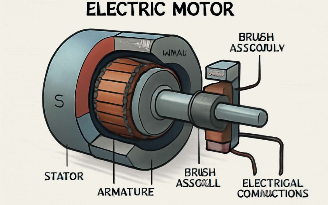
Key Components of Electric Motors
Stator
At the heart of every electric motor lies the stator, an intricate assembly that functions as the silent powerhouse behind the device’s operational prowess. Its magnetic field, carefully orchestrated within the components of an electric motors diagram, is what transforms electrical energy into rotational motion. The stator’s core, often composed of laminated steel sheets, minimizes energy losses and enhances magnetic flux efficiency, a critical factor in motor performance.
Surrounding this core are the stator windings—precise copper coils arranged in specific patterns—whose currents generate magnetic fields that interact with the rotor. The arrangement and design of these windings are paramount; they determine the torque, speed, and overall efficiency of the motor. When examining an electric motors diagram, one can appreciate how these elements coalesce into a system of meticulous engineering brilliance.
Understanding the key components of the stator reveals an essential truth: each element, from the laminations to the winding configurations, is vital in harnessing electromagnetic forces. This synergy not only powers countless machines but also exemplifies the brilliance of electrical design—an elegant dance of energy, magnetism, and precision engineering!
Rotor
Within the heart of every electric motor lies the rotor, the dynamic component responsible for converting electromagnetic energy into rotational force. It’s often regarded as the engine’s soul—turning electrical pulses into smooth, purposeful motion. The rotor’s design varies depending on the motor type, but its core function remains consistent: to respond to the magnetic fields generated by the stator and produce torque.
In an electric motors diagram, the rotor is typically depicted as a shaft surrounded by conductive bars or windings, depending on the motor’s architecture. These components work together to create a magnetic field that interacts with the stator, resulting in rotation. To optimize this process, engineers carefully select rotor materials and configurations, ensuring durability and efficiency even under demanding South African conditions.
Understanding the rotor’s key components reveals how intricately they are woven into the motor’s overall performance. From squirrel-cage rotors in induction motors to wound rotors in slip ring designs, each variation has a profound impact on the motor’s torque and speed. It’s this harmonious interplay—shown vividly in an electric motors diagram—that propels everything from small appliances to large industrial machinery across our landscape.
Commutator
Within the shadowed realm of electric motors, the commutator stands as a sinister yet vital component—the silent conductor of electrical whispers that orchestrate the motor’s dark ballet. Often overlooked in the glowing diagram of the motor, this cylindrical marvel is cloaked in copper segments, meticulously arranged to reverse current flow at precise moments, ensuring the rotor’s relentless spin.
In essence, the commutator functions as a ruthless gatekeeper, transforming the chaotic energy within the motor into a harmonious dance of magnetic forces. Its contact with brushes—those ebony filaments—creates a fleeting yet essential connection, allowing current to flow seamlessly through the windings of the rotor. This process sustains the magnetic interaction that fuels the motor’s relentless motion, even amidst the harsh conditions faced in South Africa’s industry.
- Durability against wear and tear
- Precise timing of current reversal
- Synchronization with brushes and windings
In an electric motors diagram, the commutator’s silhouette may seem simple—yet it embodies the dark poetry of electro-mechanical harmony, a vital cog in the machinery of modern industry. It’s the unseen force that keeps the ghostly pulse of the motor alive, driving progress through shadows and light alike.
Brushes
At the heart of every electric motors diagram lies the humble yet indispensable component known as the brushes. These slender filaments, often made from carbon, serve as the vital link between the stationary parts of the motor and its spinning core. Without them, the seamless flow of current would falter, and the magnetic symphony would come to a halt. In the bustling industries of South Africa, where machinery must endure harsh conditions, the durability of these brushes is paramount.
Brushes are designed to maintain consistent contact with the commutator, ensuring the precise timing of current reversal needed for smooth operation. Their placement and material composition influence the efficiency and lifespan of the motor, acting as the quiet guardians of electrical continuity. This delicate dance between brushes and commutator embodies the intricate beauty of electric motors, where every component, no matter how small, plays a crucial role.
In an electric motors diagram, understanding the placement of brushes can unlock a deeper appreciation for the motor’s inner workings. They are often depicted as dark, elongated strips hugging the cylindrical commutator, orchestrating the magnetic forces that propel the rotor forward. The synchronization between brushes, commutator, and windings is a marvel—an elegant ballet of electro-mechanical harmony that powers industries across South Africa, from mining to manufacturing.
Armature
At the core of every electric motors diagram lies the armature—an essential component that transforms electrical energy into mechanical motion with elegant efficiency. Often depicted as a series of winding coils wrapped around a ferromagnetic core, the armature’s role is nothing short of magnetic ballet. When energized, it interacts seamlessly with the stator’s magnetic field, setting the rotor in motion with a whisper of precision.
In many industrial applications across South Africa, the armature is designed to withstand rigorous operational conditions—think mining machinery or manufacturing line equipment. Its construction involves tightly wound wire coils, which are crucial for generating the magnetic flux that powers the motor. To optimize performance, engineers carefully select materials that offer durability and thermal stability.
- Winding coils: The heart of the armature, responsible for creating the magnetic field.
- Commutator contact surfaces: Ensuring the electrical connection remains stable during rotation.
- Core laminations: Reducing eddy currents for improved efficiency and heat dissipation.
Understanding the placement and function of the armature within an electric motors diagram provides invaluable insight into the motor’s smooth operation. It’s the silent workhorse, orchestrating the dance of electromagnetic forces that powers everything from South African machinery to household appliances—proof that even the smallest components can wield enormous influence in the grand symphony of industrial productivity.
Windings
At the heart of every electric motors diagram lies the winding coils—sometimes called the windings—that act as the electrical heartbeat of the motor. These intricately wound copper wires are more than just conductors; they are the creators of magnetic flux that energize the entire system. When current flows through these coils, they generate a magnetic field that interacts with the stator, setting the rotor into motion with remarkable precision.
Understanding the significance of windings is essential, especially in industries across South Africa where durability and efficiency are paramount. Properly designed windings not only boost performance but also extend the lifespan of the motor under harsh operating conditions. To achieve this, engineers select high-quality materials that resist thermal stress and mechanical wear.
Within an electric motors diagram, the placement of these windings reveals the motor’s operational elegance. They are typically wrapped around the core lamination, ensuring minimal energy loss while maximizing magnetic influence. Their strategic arrangement ensures smooth, reliable operation—whether powering mining equipment or household appliances—making windings a cornerstone of motor design and efficiency.
Common Electric Motor Diagrams
Single-Phase Induction Motor Diagram
In the intricate dance of modern machinery, the single-phase induction motor stands out as a marvel of engineering simplicity and reliability. Its electric motors diagram reveals a symphony of components working harmoniously to convert electrical energy into mechanical motion—an essential sight for anyone seeking to understand the pulse of everyday industrial and household appliances. The beauty of this diagram lies in its clarity: it maps out the stator winding, rotor bars, and the magnetic flux pathways that breathe life into the motor’s operation.
Within the electric motors diagram, the single-phase induction motor showcases a straightforward yet elegant design. Unlike its three-phase counterparts, this motor relies on a single alternating current source, making it ideal for locations where power supply is limited. Its magnetic field induces current in the rotor, creating torque through electromagnetic induction—a process that is both timeless and efficient. Exploring this diagram offers insights into how these motors seamlessly blend power and simplicity, embodying the spirit of innovation that drives industry forward.
- Stator winding configuration
- Rotor design and placement
- Magnetic flux pathways
Three-Phase Synchronous Motor Diagram
Within the realm of electric motors diagram, the three-phase synchronous motor emerges as a mesmerizing dance of precision and power. Its elegant symmetry, often depicted in detailed schematics, reveals how the stator’s winding configuration creates a rotating magnetic field that perfectly syncs with the rotor. This harmony ensures the motor runs with remarkable efficiency, making it a favorite in large industrial applications across South Africa.
The core of the three-phase synchronous motor diagram is a sequence of carefully arranged windings, energized by a three-phase power supply. As the magnetic flux pathways intertwine, they produce a steady magnetic field that pulls the rotor into a synchronized rotation—fascinating to witness in operation. Here’s what makes this electric motors diagram so captivating:
- The stator winding configuration that establishes a rotating magnetic field
- The rotor’s design, often a salient pole or salient rotor, influenced by the magnetic flux pathways
- Synchronization process that allows precise control of motor speed and torque
This intricate diagram showcases not just the beauty of engineering but also the timeless principles that underpin modern industry. Understanding the electric motors diagram of a three-phase synchronous motor unlocks a deeper appreciation for how power is harnessed and directed with such finesse, vital for industries across South Africa seeking sustainable and reliable energy solutions.
DC Motor Electrical Diagram
When it comes to understanding the ins and outs of electric motors, the DC motor electrical diagram is a cornerstone that often gets overlooked—yet it’s pivotal in deciphering how these machines convert electrical energy into mechanical motion. Unlike its more glamorous cousins, the DC motor diagram is a straightforward yet fascinating blueprint of innovation, showcasing the vital components that keep the motor humming along smoothly.
At the heart of the DC motor electrical diagram, you’ll find key elements such as the armature windings, commutator, and brushes—each playing a crucial role in ensuring the motor’s operation is both efficient and reliable. These components work in perfect harmony, allowing the motor to produce a steady torque and predictable speed. For enthusiasts and engineers alike, understanding this electric motors diagram unlocks the secrets behind the motor’s seamless performance, especially in industrial settings across South Africa.
To simplify the complexity, here’s a quick breakdown of what the typical DC motor electrical diagram highlights:
- Power supply connection
- Armature winding path
- Commutator segments switching current direction
- Brushes maintaining contact with the commutator
This detailed yet elegant diagram reveals how the flow of current through the armature windings interacts with magnetic fields, creating a force that spins the rotor. Recognizing the intricacies of the electric motors diagram not only deepens appreciation for the engineering marvel but also emphasizes the importance of precise design—especially vital when powering industries across South Africa that demand durability and efficiency.
Brushless DC Motor (BLDC) Diagram
Stepping into the realm of electric motors, the Brushless DC motor (BLDC) diagram unlocks a world of sleek, silent power—an engineering marvel that’s quietly revolutionizing industries across South Africa. Unlike traditional brushed motors, the BLDC diagram reveals a sophisticated dance between magnets and electronic switches, creating a seamless flow of energy that propels machines with remarkable efficiency. This innovative design eliminates the need for brushes and commutators, resulting in less wear and tear, and ultimately, longer-lasting performance.
At the core of the electric motors diagram for a BLDC lies an intricate network of stator windings and permanent magnets on the rotor. The precise positioning of sensors and electronic controllers orchestrates the magnetic interactions, producing smooth, precise rotation. To grasp the full potential of this motor type, it’s essential to understand the flow of current and how the electronic commutation system replaces mechanical components—an advancement that’s crucial for renewable energy applications and electric vehicles powering South Africa’s future.
Universal Motor Circuit Diagram
When it comes to understanding the heart and soul of electric motors, the universal motor circuit diagram is a fascinating blueprint. Unlike its more specialized cousins, the universal motor can run on both AC and DC power, making its diagram a flexible and intriguing puzzle for engineers—South Africa’s burgeoning industrial sector loves this versatility! The typical electric motors diagram for a universal motor highlights a simple yet clever design: a stator with windings, a rotor, and a commutator that switches current direction seamlessly.
To truly grasp how this motor works, it helps to visualize the flow of current through its components. Here’s a quick rundown:
- The stator creates a magnetic field.
- The armature (rotor) turns within this magnetic environment.
- The commutator and brushes work together to reverse current at just the right moments, ensuring smooth rotation.
This straightforward yet powerful electric motors diagram makes these motors ideal for applications demanding high starting torque, like power tools or household appliances. The beauty of the universal motor lies in its simplicity—yet it packs enough punch to power through demanding tasks, especially when the diagram is understood and optimized for specific needs in South Africa’s diverse industries.
Interpreting Electric Motor Diagrams
Symbols Used in Electric Motor Diagrams
In the intricate dance of engineering, electric motors diagram serve as a visual symphony, translating complex electrical and mechanical interactions into comprehensible symbols. Each symbol on an electric motors diagram carries a story—of currents flowing, magnetic fields colliding, and energy transforming seamlessly. To truly interpret these diagrams, one must read beyond the lines and symbols, recognizing the language of the engineer’s mind. It’s akin to deciphering a secret code that unlocks the powerful heartbeat of electric motors.
Understanding these symbols is essential, especially when troubleshooting or designing machinery that relies on electric motors. Common symbols include coils, switches, and power sources—each representing a vital component. For example, a simple circle with internal lines may denote a motor’s windings, while a zigzag line could symbolize resistors or inductors. Familiarity with these symbols transforms a static diagram into a dynamic narrative of energy and motion.
In essence, mastering the interpretation of an electric motors diagram unlocks a deeper appreciation of how these marvels of modern engineering function. It’s not just about reading symbols but about perceiving the flow of power that drives industry forward, a silent testament to human ingenuity and innovation! The beauty of these diagrams lies in their ability to condense complex systems into elegant representations—each one a gateway to understanding the marvel that is the electric motor.
Reading Circuit Connections
Interpreting electric motors diagram requires more than just recognizing symbols; it’s about deciphering a layered tapestry of electrical pathways and mechanical movements. When reading circuit connections in these diagrams, every line and junction tells a story—of currents, magnetic fields, and energy transfer—hidden beneath a seemingly straightforward sketch. The challenge lies in tracing these connections accurately, understanding how each component interacts within the system.
To make sense of an electric motors diagram, focus on the flow of power through the circuit. Look for key indicators such as switches, contactors, and power sources that define the operational sequence. A strategic approach involves following the circuit from the power input, through various control elements, to the motor windings. Recognizing how these elements interconnect reveals the motor’s control logic and operational nuances.
- Identify the starting point: power supply and main switch
- Trace control circuits: relays, contactors, and switches
- Follow the load path: windings, coils, and magnetic components
In essence, mastering the art of reading circuit connections on an electric motors diagram transforms a complex schematic into a vivid narrative of energy flow, revealing the motor’s inner workings with clarity. This skill unlocks the secret language of electrical engineers, turning static symbols into a dynamic story of innovation and functionality—an essential tool for troubleshooting, designing, or maintaining electric motors in any industrial setting.
Identifying Components and their Functions
Understanding an electric motors diagram is like unlocking the heartbeat of machinery—each symbol and connection tells a story of energy and purpose. When interpreting these diagrams, it’s essential to identify key components such as the stator, rotor, and windings, each playing a crucial role in motor operation. These elements work together to convert electrical energy into mechanical force, and recognizing their placement within the electric motors diagram can reveal how the motor starts, runs, and stops seamlessly.
To grasp the full picture, it helps to focus on the flow of electricity through the circuit. This involves tracing the path from the power source, through control devices like contactors and switches, and finally to the motor windings. Recognizing how these components interconnect is vital for troubleshooting or designing efficient systems. For example, the control circuit often includes relays or switches, which modulate the flow of current and influence the motor’s behavior.
In essence, reading an electric motors diagram transforms into a vivid narrative of electrical pathways—each line and symbol representing a vital function. Appreciating these connections deepens understanding, making it easier to diagnose issues or optimize performance. The skill of deciphering an electric motors diagram is a bridge between static symbols and dynamic energy transfer—an invaluable tool for anyone working in electrical engineering or maintenance in South Africa or beyond!
Applications of Electric Motors
Industrial Uses
Electric motors are the silent engines powering South Africa’s bustling industrial landscape. From mining operations to manufacturing plants, their applications are as diverse as the industries they serve. The electric motors diagram reveals intricate details about their inner workings, but beyond the schematic, these machines are the backbone of modern industry. They transform electrical energy into mechanical force, enabling everything from conveyor belts to heavy-duty cranes to operate seamlessly.
Industrial uses of electric motors are truly expansive. They drive HVAC systems, fuel agricultural machinery, and even power electric vehicle fleets. In fact, the efficiency of these motors directly impacts productivity and energy consumption. For instance, high-performance AC and DC motors are vital in automation processes, ensuring precision and reliability. Their versatility underscores why understanding the electric motors diagram is essential for engineers and technicians alike.
- Manufacturing equipment
- Mining machinery
- Transport systems
- Agricultural tools
Household Appliances
Electric motors have become an integral part of every household in South Africa, quietly powering the appliances that make daily life easier and more comfortable. From the rhythmic spin of a washing machine to the gentle whir of a blender, these machines rely on an intricate electric motors diagram to operate efficiently. Understanding the internal workings of these motors reveals how electrical energy transforms into mechanical motion, bringing convenience into our homes.
Common household applications powered by electric motors include vacuum cleaners, refrigerators, and air conditioners. Their reliability and efficiency are vital for maintaining a comfortable living environment, especially during the harsh South African summers. Many of these appliances utilize single-phase induction motors, which are designed for simplicity and durability, ensuring they serve households for years to come.
When you consider the array of household appliances that depend on electric motors, it’s clear that their design and functionality are more than just technical details—they impact everyday comfort and energy efficiency. The electric motors diagram not only reveals the complexity of these devices but also highlights their significance in sustaining modern, energy-conscious homes. In a region where power outages can be frequent, understanding these motors becomes even more critical to optimize their performance and longevity.
Automotive Applications
In the shadowed veins of modern machinery, electric motors pulse with an almost mystical energy, their applications extending far beyond the domestic realm into the heart of automotive innovation. South Africa’s automotive industry leans heavily on these relentless engines, where electric motors diagram reveal the intricate choreography behind silent powerhouses. From electric vehicles to hybrid cars, understanding how these diagrams translate into motion unveils a world where mechanical grace meets electrical precision.
Within automotive applications, electric motors serve as the unseen force propelling vehicles with a whisper of efficiency. They are not merely components but the very soul of clean transportation—an essential in a land craving sustainable mobility. The electric motors diagram for such systems often highlights the complex interplay between stators, rotors, and advanced control circuits, illustrating how electricity transforms into smooth, responsive movement. This synergy ensures that South African drivers experience both power and eco-consciousness with every journey.
In essence, the electric motors diagram becomes a map through which engineers and enthusiasts alike decipher the silent language of modern mobility. Whether powering the sleek electric sedans or the rugged off-road vehicles, these diagrams hold the secrets to a future where energy and innovation dance in perfect harmony. The relentless pulse of electric motors fuels not only cars but also the aspiration for a cleaner, brighter tomorrow in South Africa’s evolving automotive landscape.
Renewable Energy Systems
Renewable energy systems are transforming South Africa’s landscape, and electric motors are at the core of this silent revolution. Their role extends beyond simple mechanical motion—these motors are integral to harnessing sustainable power, making them vital for solar farms, wind turbines, and other green initiatives. The electric motors diagram for these systems reveals a complex yet elegant choreography of energy flow, illustrating how electrical input is converted into reliable, clean energy.
Understanding the electric motors diagram within renewable energy applications allows engineers and enthusiasts to appreciate the intricate balance of components—generators, inverters, and control circuits—all working harmoniously. This interconnected dance ensures efficiency and resilience, vital qualities for South Africa’s evolving energy needs. As renewable systems grow, so does the importance of deciphering these diagrams to optimize performance and sustainability. The electric motors diagram becomes not just a technical blueprint but a testament to innovation’s potential in shaping a greener future.
Tips for Creating Accurate Electric Motors Diagrams
Standard Symbols and Notations
Creating an accurate electric motors diagram requires a meticulous approach that balances clarity with technical precision. When designing these diagrams, it’s essential to adhere to standard symbols and notations, ensuring that every component, from the stator to the rotor, is represented consistently. This consistency not only streamlines the interpretation process but also minimizes errors during troubleshooting or maintenance. In fact, a well-constructed electric motors diagram can be the key to unlocking complex electrical behaviors hidden within the machine.
To enhance clarity, consider utilizing a standardized set of symbols that are universally recognized in the industry. These symbols serve as a universal language, bridging gaps between engineers, technicians, and manufacturers. Incorporating a legend or key within the diagram can further clarify ambiguities and enhance the diagram’s usability. Remember, the goal is to produce a visual map that reveals the intricate dance of electrical currents and magnetic fields within the motor, making the complex accessible to all.
When crafting your electric motors diagram, keep in mind the importance of logical component placement and clean wiring pathways. Use numbered lists or clear labels to identify critical parts, especially when illustrating complex circuits or control systems. This approach not only aids in comprehension but also ensures that your diagram serves as an effective communication tool across diverse professional disciplines. With these tips, creating precise and professional electric motors diagrams becomes less of a challenge and more of an art form—an essential skill in the realm of electrical engineering in South Africa and beyond.
Design Best Practices
Creating an accurate electric motors diagram is akin to deciphering a hidden blueprint of electrical harmony. To ensure your diagram captures the intricate dance of currents and magnetic fields, meticulous attention to detail is paramount. One effective tip is to maintain consistency in symbol usage throughout the diagram; this not only enhances clarity but also fosters seamless communication across engineering teams in South Africa’s diverse industries.
Incorporating a legend or key is essential—think of it as the Rosetta Stone for your diagram. It transforms complex symbols into a universal language, bridging gaps between technicians, designers, and manufacturers. Remember, the placement of components should follow a logical sequence, with clean wiring pathways that mirror real-world connections. This thoughtful approach prevents confusion and reduces troubleshooting time, making your electric motors diagram a powerful tool for understanding and maintenance.
- If your diagram involves control systems or complex circuits, numbering critical parts or adding clear labels can elevate comprehension. This simple step turns a dense schematic into an accessible visual map, revealing the nuances of electric motor operation—crucial for those working across South Africa’s renewable energy, industrial, or automotive sectors.
Ultimately, designing a precise electric motors diagram isn’t just about technical accuracy; it’s about crafting a visual narrative that unlocks the motor’s secrets with every line and symbol. When executed with care, your diagram becomes more than just a technical document—it transforms into an insightful guide through the motor’s unseen world.
Common Mistakes to Avoid
Crafting an accurate electric motors diagram requires more than just technical skill; it demands an eye for detail and a deep understanding of the motor’s inner workings. One common mistake is inconsistent symbol usage, which can turn a clear diagram into a confusing maze of lines and shapes. To avoid this, always double-check that each symbol aligns with standard notations—this ensures seamless communication with South African engineers and technicians.
Another pitfall is neglecting to include a comprehensive legend or key. Think of it as your diagram’s universal translator—without it, even the most well-drawn schematic can seem like an indecipherable code. Additionally, poorly organized wiring pathways or disconnected components can lead to misinterpretations, making troubleshooting a nightmare. Remember, clarity in your electric motors diagram isn’t just aesthetic; it’s crucial for accurate diagnostics and maintenance.
In diagrams involving control systems or complex circuits, failing to number critical parts or add descriptive labels can obscure understanding. This oversight often results in misaligned expectations when diagnosing faults or explaining operation. By paying attention to these details, your electric motors diagram becomes a powerful visual tool—an intuitive map revealing the motor’s secrets and ensuring smoother operation across South Africa’s diverse industries.