
The Electromagnetic Foundation
Understanding Magnetic Fields
Every spin of a motor shaft begins with interacting magnetic fields. In South Africa, where energy efficiency concerns grow daily, this interaction is not academic. It informs practical decisions about equipment maintenance and selection.
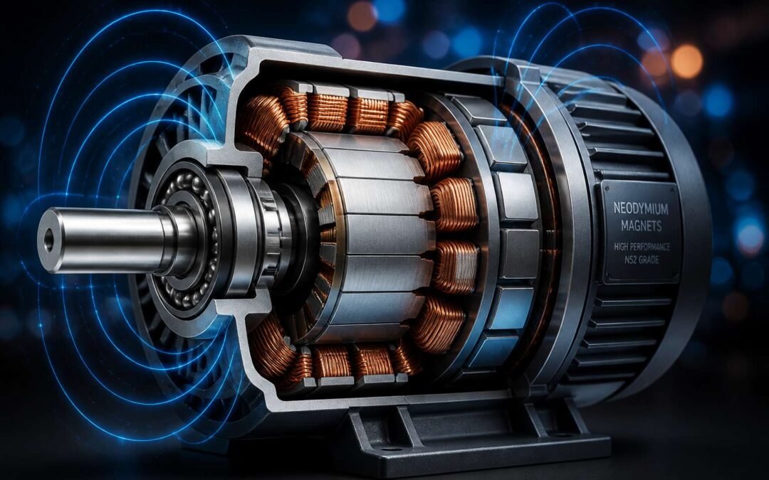
Magnetic fields are regions where force manifests without contact. When current flows through a conductor, it creates a field around it. When that conductor sits inside another field, the two interact, producing motion. Electric motors rely on the principle of this interaction to convert electrical energy into mechanical work.
When we measure field strength, we use teslas, but direction matters just as much. Field lines flow from north to south, and their density determines applied force.
Factors that shape field behaviour include:
- The amount of current flowing through the windings
- The number of coils in the armature
- The gap between rotor and stator
- The type of core material used
Each factor changes how efficiently the motor uses its input power.
The Role of Current-Carrying Conductors
There is something occult about a copper wire carrying current. It conducts no visible substance, yet transmits invisible force along its entire length. Electric motors rely on the principle of electromagnetic interaction, and that interaction begins within the conductor, where moving charge generates its own magnetic presence.
The wire works under constant pressure. Every strand of copper in the armature pushes against the stator’s field, producing torque that strains against inertia. This is not gentle work. Heat builds. Insulation ages. The constant pulse of alternating current fatigues the metal.
Conductor characteristics that dictate performance:
- Material composition determines electrical resistance and thermal threshold
- Wire diameter influences maximum current capacity before saturation
- Insulation quality dictates resistance to moisture, abrasion, and heat
Strain accumulates within the conductor without visible warning. I have watched motors fail from compromised windings. South African facilities cannot afford this silence.
Forces Generated by Electromagnets
A single electromagnet can exert force that astonishes. Copper wound around a ferromagnetic core produces magnetomotive force, the invisible energy that turns every industrial rotor in South Africa. Electric motors rely on the principle of electromagnetic induction, yet the working reality is physical coercion. Poles attract and repel in precise sequence, and that sequenced coercion becomes rotation.
Electromagnets do not generate force uniformly. Their strength depends on flux density, core material, and air gap geometry. I have watched engineers chase performance issues by adjusting these variables, only to find that thermal expansion had shifted the gap by millimetres.
- Ampere-turns determine magnetomotive force output
- Air gap width directly impacts flux linkage
- Core saturation limits maximum achievable force
These forces strain every component. The stator pushes, the rotor yields, and the motor moves.
Conversion of Electrical Energy into Mechanical Motion
The Commutation Process
Every second, electric motors across South Africa spin fans, pumps, and conveyor belts, consuming about 40% of the nation’s industrial electricity. Yet the real wonder sits inside: a simple mechanism that turns a steady flow into purposeful rotation!
The conversion of electrical energy into mechanical motion depends on the commutation process. As the rotor turns, a commutator reverses the current direction in the coil at the exact moment needed. This reversal enables the motor to keep turning. The sequence follows a precise pattern:
- Brushes slide across copper segments.
- Current switches polarity in the winding.
- Torque pulls the rotor forward.
- The cycle repeats with each half-turn.
Without this precise switching, the rotor would lock into place and motion would die. Electric motors rely on the principle of controlled interruption to sustain movement. Slip the timing, and you get sparking, heat, and failure. The commutator acts at the same point each rotation.
Torque Generation and Rotor Movement
When current courses through the rotor winding, each conductor becomes a miniature force vector. The armature’s geometry arranges these vectors in opposition, producing a twist. That twist is torque, which directly determines the rate of angular acceleration. The greater the current and the stronger the field, the more forceful the spin.
- Current magnitude in the winding
- Number of loops in the coil
- Flux density across the air gap
As torque accelerates the rotor, momentum carries it forward. But without careful timing (which we covered in the commutator section), the motion would stall. Instead, each half revolution reorients the force pair, maintaining a smooth, continuous output. Electric motors rely on the principle of torque persistence to convert electrical energy into mechanical work. Even a slight imbalance in rotor mass can cause vibration, so engineers balance every revolution.
Stator and Rotor Interactions
A three-phase induction motor converts over 85% of electrical energy into mechanical motion, yet the real work happens in the space between stator and rotor. The stator’s stationary windings produce a rotating magnetic field. The rotor, suspended within that field, picks up induced currents without any physical contact. This is the heart of the conversion process!
Here is how the interaction unfolds:
1. The stator establishes a rotating field at synchronous speed.
2. The rotor lags behind, creating slip.
3. Slip generates rotor currents, which produce rotation.
This is why electric motors rely on the principle of electromagnetic induction to turn electrical input into steady mechanical output. The stator shapes the field’s direction, while the rotor converts that invisible force into tangible motion. Each component depends on the other, from start-up to full speed.
Back Electromotive Force
When a rotor begins spinning, it generates a voltage that opposes the supply. This countervoltage, called back electromotive force, increases with speed. It effectively pushes back against the current that started it. That is why electric motors rely on the principle of electromagnetic induction, but also on this self-limiting behavior to avoid destroying themselves.
Back EMF turns a potential short circuit into a controlled process. At start-up, back EMF is absent, so current surges. As speed rises, back EMF grows and reduces current draw. The motor then operates at an equilibrium. Here is what back EMF accomplishes in practice:
- Limits current without external resistors.
- Adjusts torque automatically to load.
- Prevents windings from overheating.
The conversion of electrical energy into mechanical motion depends on this balance. Without back EMF, every motor would be a fireworks display, and not the festive kind.
Direction of Rotation and the Right-Hand Rule
Electric motors rely on the principle of electromagnetic reciprocity, yet the pathway from electrical input to rotational output follows vector mathematics. When current flows through a conductor within a stator’s magnetic field, the resulting force deflects the rotor along a predictable trajectory. The right-hand rule maps this cross product between current direction and magnetic flux.
Place the right hand so the fingers trace current flow while the palm confronts the field lines. The thumb indicates the force, hence the rotation direction. That is the method! Engineers reverse direction by swapping supply polarity or rewiring stator connections. Electric motors rely on the principle of the right-hand rule to convert electrical energy into motion without ambiguity.
- Swapping any two supply phases reverses rotation in three phase motors.
- Reversing armature connections flips direction in DC motors.
Without it, installation would rely on trial and error, an unaffordable risk for South African operations.
Different Motor Topologies
Brushed DC Motors
The brushed DC motor, a nineteenth century design, refuses to retire. In South African factories, these motors drive conveyor belts and gate motors with tenacity. While all electric motors rely on the principle of electromagnetic rotation, the brushed topology achieves torque through pure mechanical directness.
The armature spins within a magnetic field. Carbon brushes ride a split commutator, feeding current into the rotor. That contact point defines this topology.
This makes the brushed motor simple to govern. More voltage, more speed! Reverse the polarity, change direction. No electronic controller needed, keeping them cheap.
What separates a brushed DC motor from other topologies?
- Brushed motors switch current mechanically, not through external circuitry.
- They generate maximum torque right from a dead stop.
Maintenance is the tradeoff. Carbon dust collects, and brushes wear down. Yet when a technician can rebuild this motor in under an hour, the brushed DC design still makes sense.
Brushless DC Motors
All electric motors rely on the principle of electromagnetic rotation. The brushless DC motor applies this with electronic commutation instead of mechanical contacts. A controller switches current through stator windings while the rotor carries permanent magnets. The stator field rotates stepwise and the rotor follows in lockstep.
This design removes carbon brushes and the commutator entirely. No brush dust, no worn contacts. The tradeoff is a mandatory electronic controller. Brushed motors tolerate simple switches. A brushless motor without its controller sits as an inert assembly of copper and magnets.
South African applications are growing. Typical installations include:
- Computer fans in office server racks
- E-bike hub motors climbing suburban hills
- Security gate motors on residential driveways
Maintenance drops dramatically, but diagnosing faults demands more than a multimeter and patience. The controller, the hall sensors, and the winding insulation each require attention. In my experience, for many industrial drives, this complexity beats replacing brushes every few months.
AC Induction Motors
AC induction motors dominate heavy industry. All electric motors rely on the principle of electromagnetic rotation, but induction designs achieve that rotation without permanent magnets or brushes. The stator produces a rotating magnetic field. The rotor, embedded with conductive bars, carries induced currents. Those currents interact with the field to produce torque.
Two main topologies exist. Squirrel cage motors are rugged and inexpensive. They power pumps, conveyors, and compressors across South African mines. Wound rotor motors include external resistors that control starting current. That feature suits high inertia loads.
- Squirrel cage: low maintenance, high reliability
- Wound rotor: adjustable start torque, lower starting current
I have seen plants run these motors for decades with minimal attention. Efficiency varies with load, but longevity remains the strongest argument.
Synchronous Motors
Synchronous motors are the perfectionists of the motor family. They demand exactness, rotating at precisely the supply frequency, no more, no less. While induction motors tolerate slip, synchronous motors refuse it. That strict discipline makes them valuable for operations requiring constant speed, such as South African mine winding drives and crushers.
Electric motors rely on the principle of electromagnetic rotation, but synchronous machines add a twist. The rotor uses either permanent magnets or a wound field, locking onto the stator’s rotating magnetic field. They are not self-starting, so engineers add damper windings or variable frequency drives.
- Precise speed control for industrial processes
- Power factor correction for energy savings
- High efficiency under steady loads
Every engineer has watched a synchronous motor hum with quiet authority. It lacks the rugged simplicity of its induction cousin, but for heavy loads, that steady hand is worth the complexity.
Efficiency, Control, and Real-World Applications
Variable Frequency Drives
Roughly 40% of South Africa’s electricity flows through industrial electric motors. Variable frequency drives change how those electric motors rely on the principle of electromagnetic induction to deliver real efficiency. By adjusting speed to match load, a VFD can slash energy use by half in pumps and fans. I have seen mines cut their monthly power bills substantially.
Control becomes a matter of finesse. A drive enables smooth ramps up and down, sparing belts and bearings from shock. Operators can hold torque at near zero speed, which opens options that fixed-speed motors never offer. Consider the common situations:
- Water treatment plants varying flow through the day.
- Conveyors needing soft starts for heavy loads.
- Compressors that run idle when demand drops.
Real-world applications also include winches on fishing trawlers and ventilation in deep shafts. The result is longer equipment life and lower maintenance. Precision, not raw power, defines modern motor control.
Torque-Speed Characteristics
The torque-speed characteristic is the fingerprint of any motor. It maps how much twisting force the shaft delivers as rotation builds from standstill to full speed. Electric motors rely on the principle of electromagnetic induction to generate this relationship, and every load demands a particular version of it.
Efficiency comes from matching the curve to the duty. A centrifugal pump needs low torque at start and rising demand as speed increases. A crusher needs high torque immediately. When the curves misalign, the motor pulls excess current and runs hot. Understanding the shape prevents that waste.
- Constant torque loads, such as conveyors, require a flat curve across the speed range.
- Variable torque loads, such as fans, tolerate a quadratic curve that rises gently.
Control strategies rely on this same map. Soft starting battles the initial region where torque peaks and current spikes. Precise speed regulation matters only in the narrow band where the motor and load curves intersect. In South African plants, that intersection determines whether a motor hums efficiently or strains during every shift.
Industrial Automation Usage
Industrial automation in South Africa depends on the match between motor and machine. A crusher that needs instant torque stalls on a soft-start curve, while a conveyor that demands constant torque overheats if given a quadratic profile. Efficiency comes from this alignment.
Control systems refine the relationship. Direct torque control and flux weakening extend the operational band beyond the nameplate, letting one motor serve multiple duties across a shift. In automotive assembly lines and food processing plants, the motor becomes an instrument.
Consider the real-world applications:
- Mining conveyor belts benefit from constant torque delivery across a wide speed range.
- Water treatment pumps operate best with rising torque as flow rates increase.
- Packaging lines need precise speed regulation for synchronisation.
Every one of these systems runs because electric motors rely on the principle of electromagnetic induction. South African engineers who master this balance cut downtime and energy spend.
Electric Vehicle Drive Systems
Most EV owners don’t think about what happens inside the motor housing. The silent hum that follows a press of the throttle exists because electric motors rely on the principle of electromagnetic induction to convert stored battery energy into forward motion. No combustion, no exhaust pulse, just a magnetic field sweeping the rotor forward. Efficiency depends on the inverter shaping current into a perfectly timed wave.
Control algorithms manage torque delivery with a granularity that feels invisible to the driver. Regenerative braking flips the motor into generator mode, feeding energy back into the battery. This dual role is the very definition of the drive system.
Real-world applications in South Africa are expanding. Delivery fleets in Johannesburg, municipal buses in Cape Town, and mining utility vehicles in the Northern Cape all depend on the same physics. Fewer moving parts, lower maintenance costs, and instant response to the slightest pedal input make electric commercial vehicles a compelling choice.
Cooling and Thermal Management
Every electric motor generates loss heat. The copper windings and steel cores resist changing magnetic fields, producing thermal energy. Electric motors rely on the principle of electromagnetic induction, yet without proper cooling, this heat degrades insulation and weakens magnets.
Control systems monitor winding temperature in real time. Variable speed pumps adjust coolant flow, while derating protocols reduce power output under extreme conditions. In South Africa’s mining sector, utility vehicles in the Northern Cape face ambient temperatures above 40 degrees Celsius. Cooling strategies vary by duty cycle:
- Forced air: simple and effective for light loads.
- Liquid cooling: handles higher thermal loads.
- Phase-change materials: absorb heat spikes during uphill hauls.
These strategies keep motors within design limits, preserving efficiency and extending service intervals.
Failure Modes and Maintenance
Motors are stubborn but predictable. Electric motors rely on the principle of electromagnetic induction to convert electricity into motion, yet they fail most often through neglect. Efficiency drops long before a total breakdown, so control systems track power factor, current harmonics, and speed ripple. In South African paper mills, moisture ingress into junction boxes causes more unscheduled stops than any electrical surge.
We treat maintenance as an act of interpretation. Vibration analysis catches bearing spalling. Partial discharge testing exposes insulation voids. Oil analysis reveals contamination in gearboxes. Common failure modes include:
- Bearing fatigue from misalignment
- Stator winding shorts from thermal cycling
- Rotor bar fractures from frequent starting
Each failure leaves clues in the data. A competent technician reads the evidence, adjusts the maintenance schedule, and keeps production running without drama. The motor does not care. We do.