
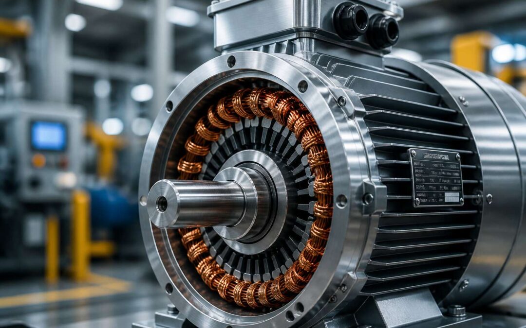
Electric Motor Varieties for Industrial Applications
AC Induction Motors: The Workhorse
Roughly 80% of fixed-speed applications in South African manufacturing run on AC induction motors. These machines convert electrical energy into mechanical work through electromagnetic induction. No brushes, no commutators! That simplicity explains their dominance.
The rotor spins because the stator’s rotating magnetic field induces current in the rotor bars. The design survives dust, heat, and salt air, making it ideal for the Highveld or coastal plants.
Common variations include:
- Squirrel cage rotors for general duty
- Wound rotor motors for high starting torque
- Explosion-proof enclosures for hazardous zones
The enclosure and insulation class determine lifespan on site. When assessing industrial electric motors, the duty cycle and IP rating matter as much as the load profile. Sizing requires precision. Oversized units waste energy. Undersized units fail early.
DC Motors: Precision and Control
When applications demand precise speed regulation and high starting torque, DC motors remain the preferred choice in South African industry. Unlike their AC counterparts, these machines convert electrical energy through direct current, allowing operators to fine tune torque across the full speed range. Mining winders, crane hoists, and rolling mills all rely on this responsiveness.
Here is where variety emerges in industrial electric motors:
- Shunt wound motors provide steady speed under varying loads.
- Series wound variants deliver exceptional starting torque.
- Separately excited designs offer independent field control.
- Permanent magnet motors eliminate field winding losses.
This precision demands maintenance discipline. Brushes and commutators require regular inspection, especially in dusty environments like the Highveld. In my years around South African plants, I have seen operators accept that burden willingly, because the control quality justifies the upkeep. The result is a motor family reserved for high performance applications rather than general duty.
Servo Motors: High-Performance Positioning
Stepper Motors: Open-Loop Simplicity
Stepping away from the closed-loop finesse of servo systems, the world of industrial electric motors reveals a different champion: the stepper motor. This device thrives on predictability and raw positional control without the need for complex feedback. Where a servo might constantly adjust its position based on sensor data, a stepper simply moves in precise, fixed increments based on electrical pulse commands. This open-loop architecture is its defining trait, offering a level of simplicity that dramatically reduces tuning time and system cost.
For engineers designing applications with defined, repeatable motions, this inherent rigidity is a massive advantage. The motor’s ability to hold its position firmly at standstill, even under a consistent load, eliminates the need for a separate braking mechanism in many designs. You are essentially commanding a digital actuator; one pulse equals one step, allowing for highly accurate speed and position control within a purely digital framework. This makes them an ideal choice for a wide array of automation tasks where repeatability is paramount and external disturbances are minimal.
Consider the distinct advantages that make stepper motors the go-to choice for many:
– Cost-Effectiveness: The absence of an encoder and complex drive logic makes them significantly more affordable than servo systems.
– High Torque at Standstill: They provide excellent holding torque, which is crucial for maintaining a load’s position without power-consuming brakes.
– Open-Loop Reliability: Without feedback components, the system is less prone to electronic noise interference and component failure.
However, the open-loop nature does have its caveats. If the mechanical load exceeds the motor’s torque capacity, the rotor can slip, losing its positional count entirely. This “lost step” condition is invisible to the controller, presenting a potential for silent errors. Therefore, the application must be designed with a strict torque margin to ensure the motor never misses a beat. When these conditions are met, the stepper motor offers an unmatched combination of simplicity and precision, a true workhorse for the uncomplicated yet exacting demands of modern industrial electric motors.
Synchronous Motors: Constant Speed Solutions
Synchronous motors might not dominate the conversation around motion control, but their role in heavy industry is absolute. Within the broad category of industrial electric motors, they represent the gold standard for operations demanding unwavering speed. Unlike their induction counterparts, a synchronous motor’s rotor locks in step with the rotating magnetic field. This means zero slip, regardless of the load variations on the shaft. For applications like ball mills, crushers, and large compressors, this constant speed is not just a preference. It is a mechanical necessity that ensures predictable output and prevents the process instability that speed fluctuations can cause.
The design does require a direct current supply to the rotor, which adds a layer of complexity. However, the payoff for this precision is substantial efficiency. They can correct the power factor of an entire facility, potentially lowering electricity demand charges. When examining the operational advantages, the benefits are clear:
– They maintain a precise speed under varying loads.
– They improve overall plant power factor, reducing utility penalties.
– They offer high torque at standstill, ideal for starting heavy equipment.
– They are designed for very high power ratings, often in the megawatt range.
This ability to stabilize the electrical grid while providing brute mechanical force is a dual role few other motors can claim. While the upfront cost is higher and the starting requirements often involve a pony motor or a variable frequency drive, the long-term payback in energy savings is significant. For a plant manager in South Africa looking at rising electricity tariffs, the power factor correction alone can justify the investment. It is a machine built for endurance and steadfastness, the quiet anchor of a modern processing plant.
Efficiency and Performance Indicators
Energy Efficiency Classes and Standards
In the realm of heavy industry, a startling 70% of electrical energy consumed by manufacturing facilities flows directly through industrial electric motors. This means the choice of motor and its efficiency classification shapes not only operational costs but the entire environmental footprint of a factory. Energy efficiency classes, defined by standards like IEC 60034, serve as a roadmap for navigating this crucial decision. Each class, from IE1 to IE4, represents a measurable step towards converting input power into mechanical work with minimal waste.
These standards are not arbitrary markers; they are the result of rigorous testing and international cooperation to promote sustainable industrial growth. Premium efficiency motors, those meeting the IE3 or IE4 levels, often employ advanced copper rotors and optimized steel laminations to reduce electrical losses. However, the operational context matters. An IE2 motor running at full load for 24 hours might still outperform an IE4 motor operating under inefficient partial-load conditions. Therefore, considering the entire drivetrain and duty cycle is essential for realizing true savings.
Selecting the right energy class involves understanding several factors beyond the initial purchase price:
- The annual operating hours and specific load profile of the application.
- The local electricity tariff and potential for rebate programs.
- The compatibility with existing variable speed drives or control systems.
These variables dictate the payback period for a higher investment in premium machinery. In South Africa, where energy security and cost are paramount, aligning with these international classes ensures that operations remain competitive and resilient. The standards also foster a common language for engineers and procurement specialists, simplifying asset management. Ultimately, a commitment to higher efficiency classes is a direct investment in operational certainty and resource stewardship.
Power Factor and Its Impact on Operating Costs
Power factor is the spectral ghost haunting every industrial electric motor, yet few operators see it. It measures how effectively electrical energy transforms into mechanical work. A perfect score of 1.0 means pure, obedient power. Most motors, however, stumble far below this ideal, typically between 0.7 and 0.85. The missing portion never disappears. It sloshes back into the grid as unusable reactive power, doing nothing except inflating your utility bill.
The penalty for a poor power factor is not theoretical. Utilities in South Africa, like Eskom, charge for apparent power rather than just the useful kilowatt-hours you consume. A lagging power factor forces the grid to supply excess current, heating transformers and straining distribution lines. Your facility eats this surcharge quietly, month after month, as though paying rent for energy that never entered the building. This hidden cost can add up to five percent of your total electricity spend.
Several losses coalesce to drag down the power factor of industrial electric motors. Lightly loaded motors draw magnetizing current that stays constant regardless of output. Older rewound units often lose their original magnetic integrity. And mismatched voltage supplies, either too high or too low, corrupt the phase angle between current and voltage. Each of these factors stacks its own tax onto your operational ledger.
– Reactive power demand charges from the utility
– Increased current flow causing I²R losses in cables and transformers
– Reduced system capacity, forcing premature capital upgrades
– Accelerated thermal aging of insulation systems
You cannot simply buy a higher efficiency motor and assume the power factor corrects itself. Efficiency and power factor are twin siblings, but they do not always agree. A premium motor with excellent efficiency can still exhibit a mediocre power factor under certain operating conditions. The true fix lies in correcting the phase angle directly, often with capacitor banks, or using variable speed drives that manage the power electronics internally.
For engineers managing fleets of industrial electric motors, the power factor deserves a place on the monthly scorecard alongside temperature and vibration. Measuring it costs little from a handheld meter or the drive’s own telemetry. Acting on it, whether through passive correction or active front-end drives, converts an invisible leak into measurable savings. In a country where every megawatt matters, losing energy to a lagging cosine is a quiet betrayal of your own bottom line.
Torque-Speed Characteristics Across Types
All industrial electric motors have a unique torque-speed curve. That curve defines how they respond under load. Ignoring it means paying for performance you never receive!
Induction motors let torque fade as speed climbs, ideal for steady loads. DC motors deliver a linear rise, giving you direct command. Servo motors hold torque across a wide range, while steppers prioritize holding over spinning.
- Locked rotor torque for startup
- Pull-out torque for stability limits
- Rated torque for continuous duty
Synchronous motors maintain perfect speed, even under heavy load, but that rigidity can break tools. Match the curve to the demand. I have seen plants waste thousands by selecting the wrong characteristic.
Thermal Management and Cooling Methods
Heat is the direct result of inefficiency in any motor system. When an industrial electric motor converts electrical energy into mechanical motion, a portion is always lost as thermal energy. This is not a minor inconvenience; it is the primary factor that determines the lifespan of your insulation system and bearings. For every 10°C increase in operating temperature above the rated limit, the life of the insulation is halved. That is a brutal mathematical reality that many plant managers learn only after an unexpected failure halts production.
Thermal management is not just about slapping on a bigger fan. It is a strategic calculation involving ambient temperature, altitude, duty cycle, and the specific cooling method employed. You must consider the Total Losses, which include both fixed losses (core losses) and variable losses (copper losses). The efficiency of your unit is directly tied to how effectively you can mitigate these thermal stressors. A motor running hot is a motor running inefficiently, and it is silently inflating your energy bill every single second it operates.
To achieve optimal performance, you need to match the cooling method to the application. The options are distinct and each has a specific place:
1. TEFC (Totally Enclosed Fan Cooled): Best for dusty or dirty environments, using an external fan to blow air over the finned frame.
2. IC 416 (Force Ventilated): Utilizes a separate blower for constant airflow, ideal for variable speed applications where the shaft fan loses effectiveness at low RPM.
3. Water Cooling (IC 86W): Uses a heat exchanger with water circulation for high-power density applications where air cooling is insufficient.
Monitoring is equally critical. You cannot manage what you do not measure, and this is especially true for heat. Installing thermocouples in the stator windings and RTDs on the bearings gives you a real-time window into the health of your machine. This data allows for predictive maintenance rather than reactive firefighting. In South Africa, where ambient temperatures can soar and energy costs are volatile, neglecting this aspect of motor care is a direct hit to your bottom line. The heat generated is the enemy of longevity, and controlling it is the single most effective way to protect your capital investment in industrial electric motors.
Noise and Vibration Signature Analysis
The quiet hum of a healthy motor is something many take for granted. That hum is a tale of precision and balance, a story told in decibels and frequencies. When that story turns into a harsh rumble or a piercing whistle, it is not a mystery; it is a confession. The machine is telling you exactly where it hurts, and learning to listen can save you from catastrophic downtime. Our previous discussions on heat management covered one half of the survival equation; this is the other half.
Vibration is the physical manifestation of stress, and noise is its acoustic shadow. In the world of rotating equipment, there is no such thing as silence; there is only a baseline. When the baseline shifts, it suggests a mechanical change. It could be a bearing losing its race, a rotor falling out of balance, or an alignment drifting due to thermal expansion. Capturing this data is non-negotiable for longevity.
For those managing critical processes, I suggest a three-step ritual to demystify the data and prevent unscheduled stops:
1. Establish a Baseline: Record the vibration spectrum and sound pressure levels during installation or after a verified, perfect overhaul. This is your control group.
2. Trend the Data: Do not just take a snapshot. Compare monthly or weekly readings to identify micro-increases in amplitude that are invisible to the human ear.
3. Analyze the Signature: Learn what the peaks on a Fast Fourier Transform (FFT) chart mean. A spike at 1x running speed often indicates imbalance, while a spike at harmonics often indicates looseness.
This is where the budget lives or dies. A motor that begins to vibrate at 0.15 inches per second may still run, but it is consuming more energy to do so. That inefficiency is the cost of ignoring the symptom. By the time you can physically feel the vibration with your hand, the wear has already advanced to a stage where replacement, not repair, is often the more economical choice.
Modern condition monitoring tools have evolved. We now have wireless accelerometers that stream real-time data to your phone, allowing you to check the health of an asset from Johannesburg to Cape Town. This is not science fiction; it is the standard for proactive facilities. By addressing a rising noise floor or a new vibration spike immediately, you transition from being a firefighter to being a surgeon. You fix the small issue with a simple lubrication or alignment adjustment, rather than performing a transplant. In the realm of industrial electric motors, these signature analyses are your insurance policy against the unexpected, and they remain the most reliable way to ensure your operation never falls silent.
Duty Cycle Ratings and Operational Limits
A motor’s nameplate reveals its peak capability, but the real story lies in how it behaves under pressure. Efficiency is not a fixed number; it is a curve that shifts with load. Most industrial electric motors reach their optimal efficiency between 75% and 95% of full load. Operating outside this sweet spot punishes your energy bill with reactive power penalties and unnecessary heat.
The Performance Index, or PI curve, offers a deeper look. It charts power factor against torque ripple across the operational spectrum. You want a flat profile. A sharp dip at a specific speed often indicates a mechanical resonance point or an electrical anomaly like a broken rotor bar. Catching these troughs on paper prevents a catastrophic failure on the floor.
Duty cycle is the silent negotiator in the motor’s lifespan. A motor rated for continuous duty (S1) will overheat quickly if you force it into an intermittent starting regime (S3). Conversely, a motor designed for short-time operation (S2) will run indefinitely if you derate its output appropriately.
Consider these operational limits to protect your assets:
- Monitor winding temperature via embedded thermistors, not just surface heat. Hot spots develop internally long before the frame feels warm.
- Verify voltage imbalance between phases stays below 1%. A 3.5% imbalance can increase winding temperature by 25%.
- Check the insulation resistance monthly. A steady decline predicts moisture ingress or winding contamination.
The South African context adds a layer of complexity. High ambient temperatures and frequent load shedding force motors into brutal cycles. A motor that handles a 50% load in Cape Town might struggle with that same load in Upington during a heatwave. You must apply a service factor that reflects your environment, not just the manufacturer’s conservative lab data.
Efficiency is ultimately a financial equation. A 2% gain in motor efficiency on a 100 kW unit running two shifts saves roughly R40,000 a year in electricity. Over a decade, that savings pays for a brand new premium motor. The data tells you where the money is hiding. The duty cycle tells you how fast you can dig it out. The operational limits tell you the price of ignorance. Respect all three, and your motor becomes a revenue generator instead of a liability line item.
The mechanical health of the unit—its vibration, its noise, its thermal signature—feeds directly into this economic model. When a bearing starts to fail, efficiency drops, duty cycle lengthens, and operational limits narrow. That hidden fault is a direct deduction from your bottom line. The motor’s manual might state its rated output, but the equipment’s true capability is dictated by the maintenance history you keep. That documented history is your ultimate safeguard, your roadmap, and your proof of operational excellence. It turns a spinning cylinder into a predictable, profitable asset.
Maintenance Strategies for Longevity
Predictive Maintenance and Condition Monitoring
The run to failure mindset is a costly gamble for any operation. A spun bearing or scorched winding can halt an entire production line for days. Predictive maintenance flips this reactive approach on its head. Instead of waiting for a breakdown, you monitor the equipment in real time, listening for the subtle clues that signal an impending failure.
Condition monitoring for industrial electric motors has moved far beyond simple visual inspections. You can now track vibration spectra to identify bearing wear and rotor bar issues. Thermographic imaging reveals hotspots in windings before insulation breakdown occurs. Oil analysis on geared motors exposes particulate contamination that would otherwise go unnoticed. These methods generate a stream of data that, when analyzed properly, gives you a clear window into the health of your assets.
- Vibration analysis for bearing and alignment faults
- Motor current signature analysis for rotor defects
- Ultrasonic testing for partial discharge activity
Think of it as moving from a scheduled checkup to a continuous conversation with your machinery. The data is the language, and the trend lines are the narrative. I will tell you this, the cost of a single unscheduled shutdown often exceeds the entire annual budget for a sophisticated monitoring system. The advantage is not just avoiding failure, it is optimizing the entire life cycle of the motor.
Vibration Analysis for Bearing and Rotor Health
Here is the content for the section on Maintenance Strategies for Longevity: Vibration Analysis for Bearing and Rotor Health:
Some plants treat their motors like neglected employees, only paying attention when they scream for help. Conversely, a solid maintenance strategy uses vibration analysis to hear the scream before it ever leaves the throat. This specific technique is the difference between replacing a R1000 bearing and replacing a R150,000 motor complete with a full production stoppage.
You can debate the exact cause, but the cure is always data. Vibration analysis pinpoints bearing wear, misalignment, and rotor bar defects. It tells you exactly where the energy is being wasted. For industrial electric motors, this is the non-negotiable health check that pays for itself every single time you catch a fault. The motor will tell you its life story through its vibrations, you just need to be willing to listen.
This is how you avoid the panic of an unexpected failure.
Lubrication Practices for Extended Bearing Life
Proper lubrication separates a bearing that runs for years from one that fails unexpectedly. For industrial electric motors, the grease film is the only barrier between metal surfaces moving at high velocity. A missed service plan creates friction, then heat, then failure.
Under-lubrication causes metal on metal contact. Over-lubrication builds pressure and heat. Both shorten bearing life. A disciplined schedule prevents both.
- Use the correct grease type for the motor’s speed and load.
- Apply the exact amount specified by the manufacturer.
- Record every service date to identify wear patterns.
Skipping this precision turns a routine maintenance task into a capital expense.
Insulation Testing and Winding Diagnostics
The quiet hum of a production line often masks a hidden threat. Overheating is the primary culprit behind premature motor failure, yet it is a symptom that manifests long before the final breakdown. By the time a thermal overload relay trips, significant damage has already occurred to the delicate copper windings. The insulating varnish that protects these conductors degrades rapidly under sustained heat, losing its dielectric strength and eventually leading to a phase-to-phase short.
To prevent this, maintenance teams must perform regular diagnostic testing. Insulation resistance testing, often performed with a megohmmeter, provides a baseline measurement of the motor’s health. A reading that drops suddenly indicates moisture ingress or contamination. For a more thorough analysis, a surge test can identify weak spots in the winding insulation that a standard resistance test might miss.
Implementing a consistent testing schedule is essential for any facility relying on industrial electric motors.
– Track the polarization index to assess winding cleanliness.
– Compare current readings against baseline data to spot anomalies.
– Schedule testing after any rewinding or extended downtime.
These practices allow you to replace a motor during a planned shutdown rather than facing an emergency failure that halts production. A modest investment in diagnostic tools pays for itself by eliminating costly downtime and extending the operational life of your most critical machinery.
Bearing Replacement Indicators and Procedures
The quiet operations of a facility often make the failure of a bearing seem abrupt, a sudden shriek of metal that surprises everyone. Yet the truth is far more measured. Vibration data will show a steady climb in high frequency energy weeks before the audible alarm, a telltale progression that many maintenance logs miss. When that energy shifts from high frequency ultrasonic signatures to lower frequency harmonics, the bearing is no longer just wearing, it is deforming. Catching this window is the only way to turn an emergency repair into a scheduled intervention.
Reading the indicators requires a disciplined eye. The rust-colored residue weeping from a bearing housing is often mistaken for oil, when it actually signals that the grease has burnt off and the races are grinding against themselves. A motor that runs a few degrees hotter than its historical norm during the same load cycle also points to windage or friction changes inside the housing.
– Unusual axial movement of the shaft that increases with load
– A distinctive low frequency thumping that syncs with the motor’s rotational speed
– An increase in operating temperature without a corresponding rise in ambient conditions
When a bearing crosses that threshold, the procedure for replacement is as much about technique as it is about parts. The coupling must be checked for angular misalignment before the motor is ever unbolted, since misalignment is the leading root cause of repeat failures in industrial electric motors. Once the motor is on the bench, induction heating of the new bearing is critical because a torch creates uneven thermal expansion that distorts the bearing envelope. The inner race must seat against the shaft shoulder without being driven with a hammer, which can fracture the race ring internally.
The most subtle step involves verifying the internal clearance after assembly. A dial indicator mounted on the end of the shaft measures residual axial play, which must align with the manufacturer’s specification for the motor’s frame size. Any play that feels excessive on smaller units indicates a press fit that was too loose. This level of scrutiny is what separates a motor that runs for ten years from one that tears itself apart in a matter of months.
Selecting the Right Motor for Your Operation
Matching Load Types: Constant vs. Variable Torque
Mismatched torque is a leading cause of premature motor failure, often costing operators more in downtime than the motor itself. Selecting the right industrial electric motors for your machinery isn’t about picking the highest horsepower; it is about understanding the mechanical demands of the driven load.
Constant torque applications require the same amount of turning force from zero speed up to full speed. Conveyors and positive displacement pumps are classic examples. Here, you face a rigid physical relationship:
– The motor must provide high starting torque to break inertia.
– The motor must maintain torque as speed increases.
– The motor must handle peak torque without stalling, especially under heavy load.
Variable torque applications are drastically different. Fans and centrifugal pumps are the standard examples. Their resistance increases with the square of the speed. At half speed, the load requires only a quarter of the torque. Selecting an oversized motor here is a mistake because it operates inefficiently across the entire speed range. Using a variable frequency drive to slow the motor in these systems delivers significant energy savings. When you compare the load profile against the motor’s speed-torque curve, the correct choice becomes clear. Match the motor’s capabilities to the load’s exact requirements, and you will avoid overheating the windings or wasting energy, ensuring the industrial electric motors work as intended for years.
Environmental Factors: Temperature, Humidity, and Corrosion
Selecting industrial electric motors for a facility requires a thorough assessment of the surrounding environment. Heat, moisture, and corrosive agents are not minor considerations; they are primary factors that dictate the motor’s longevity and reliability. A motor operating in a steel mill or a mining operation encounters conditions that will rapidly degrade standard components, making enclosure selection and material compatibility critical decisions.
The thermal load is often the first challenge. High ambient temperatures reduce the motor’s ability to dissipate internal heat, demanding insulation systems rated for higher thermal limits. Similarly, humidity and condensation create a conductive path for electrical failures. Coastal plants or chemical processors face corrosive atmospheres that attack the frame and the internal windings. The correct approach involves matching the motor’s specification to these specific threats.
– Temperature: Use Class F or H insulation where ambient heat is excessive.
– Humidity: Specify space heaters to prevent condensation during downtime.
– Corrosion: Choose a Totally Enclosed Fan Cooled (TEFC) enclosure with epoxy or stainless steel finishes for harsh chemical exposure.
By reviewing these factors against the operational site, you prevent premature failures. The goal is not to find a motor that simply fits the horsepower rating, but one that withstands the environment where it will work. Ignoring these variables leads to repetitive maintenance cycles and unexpected production halts. The investment in a motor with proper environmental protection directly reduces the total cost of ownership for the equipment.
Duty Cycle and Starting Frequency Considerations
Every manufacturing operation asks its equipment a single question: can you withstand the demands of the shift? The duty cycle is the definition of that stress. An S1 continuous rating appears simple, yet it often ignores the reality of load variations. Conversely, an S4 or S5 rating accounts for intermittent running, starting, and electric braking. Misreading these definitions leads to motors sized for the wrong thermal reality. The motor does not fail from the work. It fails from the heat generated by the start.
The frequency of starting is a hidden variable. Across South African industries, from beverage bottling to mining conveyors, high starting frequency is the primary killer of standard specifications.
– For high inertia loads, the starting current creates excessive stator heat.
– Frequent starts demand a motor with a higher service factor and specific rotor design.
– Control logic must manage the number of starts per hour to preserve winding life.
I have seen motors destroyed by a control system that cycled the load every minute. The selection process must include the “starts per hour” limit as a fixed parameter, not an afterthought. Choose a motor that views the cycle as normal, not as an exception. The cost of under-specifying is not the motor price tag; it is the lost production during the peak shift, which is far more expensive. For hoists or presses, the starting torque requirement changes the thermal profile completely, demanding a motor rated for high breakaway torque. The duty cycle is the mathematical truth of your operation, and industrial electric motors must be matched to that truth or they will fail prematurely.
Ingress Protection Ratings and Enclosure Selection
The sandy grit of a maize mill in the Free State or the salt-laden mist rolling off the Durban harbour: these are the true testing grounds for industrial electric motors. A motor’s thermal capacity means little if its internal windings are exposed to the elements. Ingress Protection ratings are the language we use to define the boundary between the internals and the environment.
The IP code is a two-digit standard. The first digit defines defence against solid objects, from a hand to fine dust. The second digit covers moisture. For a standard indoor application, an IP55 rating provides a solid barrier against dust and low-pressure water jets. This is often the baseline specification for many food and beverage operations. However, conditions shift with geography.
Consider the following specifications based on typical South African environments:
1. IP55: For indoor, dry, or occasional wash-down areas. Standard protection against dust and light moisture.
2. IP65: For dusty environments like feed mills. Full dust-tight protection and resistance to water jets.
3. IP66: For heavy wash-down environments found in dairies or abattoirs.
Selecting a higher protection grade than necessary introduces a different problem: heat retention. A fully sealed enclosure cannot breathe as effectively. This increases the operating temperature of the windings and can shorten the life of the insulation system. The specification of industrial electric motors must balance the risk of contamination against the risk of overheating. A motor that is perfectly sealed but constantly over-thermals will fail just as quickly as one exposed to dust. The environment does not just dictate the enclosure type; it dictates the thermal design and the maintenance schedule required to keep the machine running.
Sizing for Optimal Efficiency and Starting Capability
Sizing an industrial electric motor requires a delicate balance between efficiency and raw starting power. A common mistake is choosing a motor based solely on continuous load. This approach often leads to a unit that operates beautifully under normal conditions but struggles during startup. The real challenge occurs when the motor must overcome initial inertia. A motor sized for peak load can handle these demands but may operate inefficiently during lighter duty cycles, wasting energy and increasing operational costs.
To avoid this pitfall, consider the specific application requirements:
– Breakaway torque needed to start the load from a standstill.
– Peak demand during the operational cycle, versus typical running load.
– The duty cycle, defined as the frequency of starts and stops.
A properly sized motor handles frequent start-stop scenarios without excessive heat buildup, a primary cause of premature failure. Ignoring these factors forces the motor to work harder, drawing higher amperage and generating excess heat. This is why the starting capability is just as important as the running efficiency.
Integration with Control Systems and Drives
Three out of every four industrial electric motors on Earth consume more energy than they convert into mechanical work. The loss transforms into heat, vibration, and noise. In South Africa, where energy costs continue to climb, this inefficiency exacts a toll on the bottom line. Selecting the right motor for your operation extends beyond matching the physical dimensions and mounting orientation.
The modern facility requires a coordinated approach. When you integrate variable speed drives with your motor choices, you unlock the ability to match output precisely to the demand. This is where true savings emerge. A motor that ramps up slowly avoids the destructive inrush of current that accompanies direct on line starting. The drive offers soft start capability, which protects both the motor and the driven equipment from mechanical shock. This integration demands a degree of compatibility. The drive must respect the motor’s voltage rating, insulation class, and thermal limits.
Consider how the drive affects the entire system:
– It eliminates the need for mechanical control valves or throttling devices.
– It enables precise speed regulation across a wide operational range.
– It provides diagnostic data on motor health and operational parameters.
– It reduces the mechanical stress on gears and couplings during acceleration.
– It allows process speeds to change without stopping the production line.
The relationship between motor and drive is a delicate one. When you add a drive to an existing motor, the drive alters the voltage waveform. This introduces harmonics and additional heating. A motor designed for sine wave power may run hotter when fed by a drive unless you derate it or specify an inverter duty motor. The motor windings must withstand the voltage spikes from the drive’s switching action. The cable length between the drive and motor also matters, as long runs can amplify these reflected waves and stress the insulation.
Your selection should treat motor and drive as a single unit, designed to work in concert. This ensures the protection settings, the cooling requirements, and the thermal overload sensors all speak the same language. The result is a system that responds to load changes without hesitation. The motor accelerates smoothly, operates efficiently at partial load, and decelerates without mechanical strain. This integration transforms the motor from a simple rotating machine into an intelligent component of the production process. The motor becomes one part of a coordinated electrical and mechanical ecosystem that yields longer service life and lower operational expenses.
Advances in Motor Technology
Smart Motors with Embedded IoT Sensors
Advances in motor technology have transformed the modern industrial landscape. The era of the “dumb” machine is ending, replaced by the rise of the smart motor. These new units, integral to the broader category of industrial electric motors, are no longer just power converters. They are now active data nodes. By embedding IoT sensors directly into the motor housing, operators gain real-time visibility into heartbeat metrics like winding temperature, vibration spectrum, and bearing condition. This shift from reactive maintenance to predictive strategy is a fundamental change in how we approach asset management.
Consider the tangible operational benefits this connectivity brings to a facility:
– Reduced downtime through alerts that flag anomalies before they become failures.
– Lower energy bills via automatic speed adjustments based on live load demands.
– Extended equipment lifespan by preventing chronic overwork and overheating.
This embedded intelligence allows maintenance teams to shift their focus from routine checks to strategic interventions. For South African operations facing unique grid volatility, this technology offers resilience. A motor that can self-diagnose and adjust its consumption profile is an asset that protects production throughput, ensuring your machinery whispers its needs to you, instead of shouting in catastrophic failure.
Variable Frequency Drives for Dynamic Speed Control
Variable frequency drives have fundamentally changed how we think about speed control in industrial electric motors. The old approach of running a motor at full speed and then using mechanical methods to slow things down is obsolete. VFDs allow operators to adjust the motor’s speed electronically, which is far more efficient and precise. This precision is everything in industries where production quality depends on consistent throughput.
In South Africa, where energy costs are high and grid stability can be unpredictable, the ability to manage motor speed directly translates into tangible savings. A motor running at half speed does not consume half the energy; it consumes considerably less. This judicious use of power is crucial for a manufacturer aiming to stay competitive. The financial impact of implementing VFDs across a facility can be significant, often yielding a rapid return on investment.
The operational advantages are compelling:
– Energy Efficiency: Matching motor speed precisely to demand eliminates wastage.
– Process Control: Achieving consistent product quality through fine-tuned speed regulation.
– Reduced Stress: Soft starting capabilities minimize mechanical shock on belts and gears.
Beyond the immediate savings, VFDs help protect the motor itself. Direct-online starting subjects a motor to a massive inrush of current and torque. This violent start can wear down windings and stress couplings over time. VFDs provide a gradual ramp-up, a gentle acceleration that extends the lifespan of the equipment. This longevity is a strategic asset, minimizing downtime and avoiding the substantial costs of premature replacement.
For any operation relying on heavy machinery, the shift to variable frequency drives is a decisive move toward greater resilience. Industrial electric motors equipped with this technology are no longer single-speed consumers; they become adaptable assets. They respond to the dynamic needs of your production line, ensuring that every unit of electricity is used with maximum efficacy. The benefits, from reduced utility bills to enhanced machinery reliability, make a powerful case for modernisation.
Energy-Efficient Rewinding and Retrofit Options
Rewinding an industrial electric motor used to be a simple matter of replacing broken copper. That practice is now a strategic decision. The old methods of stripping and rewinding a motor core often introduced damage to the laminations. This damage silently increased eddy current losses. Those losses show up as heat and a higher electricity bill. The modern craft involves core loss testing before the rewind even begins. It also requires the use of higher grade insulation and magnet wire that matches or exceeds the original specifications.
This changes everything for a South African facility looking to extend the life of its motor assets without a total replacement. A professional rewind can restore an industrial electric motor to its original efficiency class, or even better it. You retain the original frame, the shaft, and the mounting configuration. This avoids the often-significant mechanical modifications needed for a new motor that might not perfectly align with your existing driven equipment.
Energy efficiency is now the central consideration in any motor overhaul. The options are clear and measurable:
– Core loss testing to determine if the stator is worth rewinding
– Use of inverter rated wire if the motor will pair with a variable speed drive
– Precise winding tension and forming to maintain the original air gap
– Proper varnish treatment to dissipate heat and protect against vibration
The decision to repair versus replace requires hard data. For an industrial electric motor that runs continuously, the electricity consumed in just one year can far exceed the purchase price. A sloppy rewind that drops efficiency by even a few percentage points will bleed money for a decade. A meticulous rewind does the opposite. It preserves the investment in the existing machine and ensures that the entire drivetrain, from the couplings to the gearbox, continues to operate as a balanced system. The future of motor maintenance is not about discarding assets. It is about the intelligent refurbishment of them. It requires a supplier who understands the physics of magnetic fields, not just the art of soldering.
Permanent Magnet Motors and Rare-Earth Materials
Permanent magnet motors alter torque density rules. Unlike induction machines, they generate rotor flux without drawing magnetising current. That trait alone slashes energy losses. The secret lies in rare earth alloys, particularly neodymium iron boron, which store astonishing magnetic energy in a compact volume.
For South African industry, this means smaller frames delivering the same work as larger legacy units. The catch is cost and supply volatility. Rare earth prices fluctuate with geopolitical tides. A prudent buyer must evaluate lifecycle economics.
Consider these advantages:
- Higher efficiency across partial loads
- Reduced rotor losses and cooler bearings
- Compact footprint for retrofits
Yet permanent magnet motors demand drive tuning. Their back EMF can pose risks during faults. For industrial electric motors in harsh environments, demagnetisation is a threat. Thermal monitoring and magnet grade selection mitigate that risk. The technology is not a universal cure, but for the right application, it offers a clear advantage.
Switch Reluctance Motors and Emerging Designs
Switched reluctance motors offer a distinct advantage for industrial electric motors in harsh environments. With no rotor windings or magnets, they tolerate heat, dust, and vibration that would compromise a permanent magnet unit. The catch has always been torque ripple and acoustic noise, but emerging designs are tackling those. Advanced rotor geometries and digital power electronics now smooth the torque profile, while sensorless control algorithms cut system cost.
For South African operations, from deep-level mining to steel rolling, SRMs provide fault-tolerance that keeps lines moving during grid disturbances. They also run efficiently across a wide speed range, suiting variable loads.
– Reduced maintenance: no magnet demagnetisation risk.
– High starting torque for heavy conveyors.
– Regenerative capability returns energy to the grid.
New topologies even combine SRM rotors with permanent magnet stators, blending ruggedness with higher power density. These hybrid designs are poised to become a staple for industrial electric motors in dusty plants and demanding applications, especially where uptime outweighs initial expense.
Efficiency Standards and the Move to IE5-Level Performance
Efficiency standards for industrial electric motors are no longer a tick-box exercise. They are a direct lever on your bottom line. The shift from IE3 to IE4 has been significant, but the real game changer is the arrival of IE5 class performance. This level pushes efficiency beyond 96 percent in many configurations, slashing energy losses that previously bled out as heat.
For South African operations battling rising electricity tariffs, this translates to tangible savings. A motor running at IE5 does not just consume less power; it also runs cooler. That lower thermal load extends insulation life and bearing grease longevity, which means less unplanned downtime.
The path to IE5 is not a single technology. Premium efficiency relies on a combination of advanced materials and smarter control:
– High-grade electrical steel laminations that reduce core losses.
– Copper rotors that lower resistive losses compared to aluminium.
– Integrated drives that optimise flux levels at partial loads.
Adopting this level of performance requires a slightly higher upfront investment. The payback period, however, is often startlingly short. In high-duty-cycle applications like pumps and compressors, the energy savings can recover the premium in under two years. For a continuous process, that is free money after the break-even point. The technology is available now, and it is the most direct way to cut operational costs in any facility relying on industrial electric motors.